Torque-controlled tightening
Screw capping is usually chosen for threaded closures where consistent torque is needed without damaging the cap, thread or bottle.
Screw cappers
Bottle screw cappers for plastic and glass containers where repeatable torque, cap presentation and bottle control determine production reliability.
Specification focus
Use this page to narrow the specification around this bottle machinery family before requesting a quote.
Screw capping is usually chosen for threaded closures where consistent torque is needed without damaging the cap, thread or bottle.
Guides, belts, chucks, spindles or capping heads are selected around bottle shape, stability and line speed.
A screw capper can be specified for operator cap placement, automatic cap feeding or full integration with a filling and labelling line.
Relevant equipment
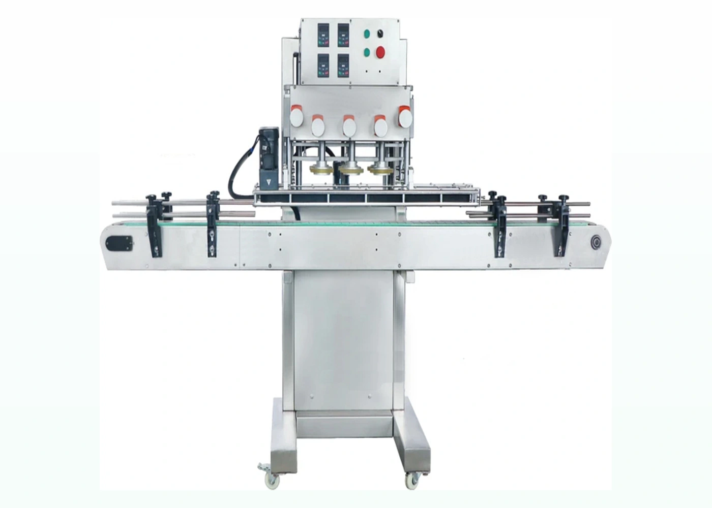
Screw cappers
Inline bottle capper for threaded closures where repeatable torque, bottle control and continuous output are important.
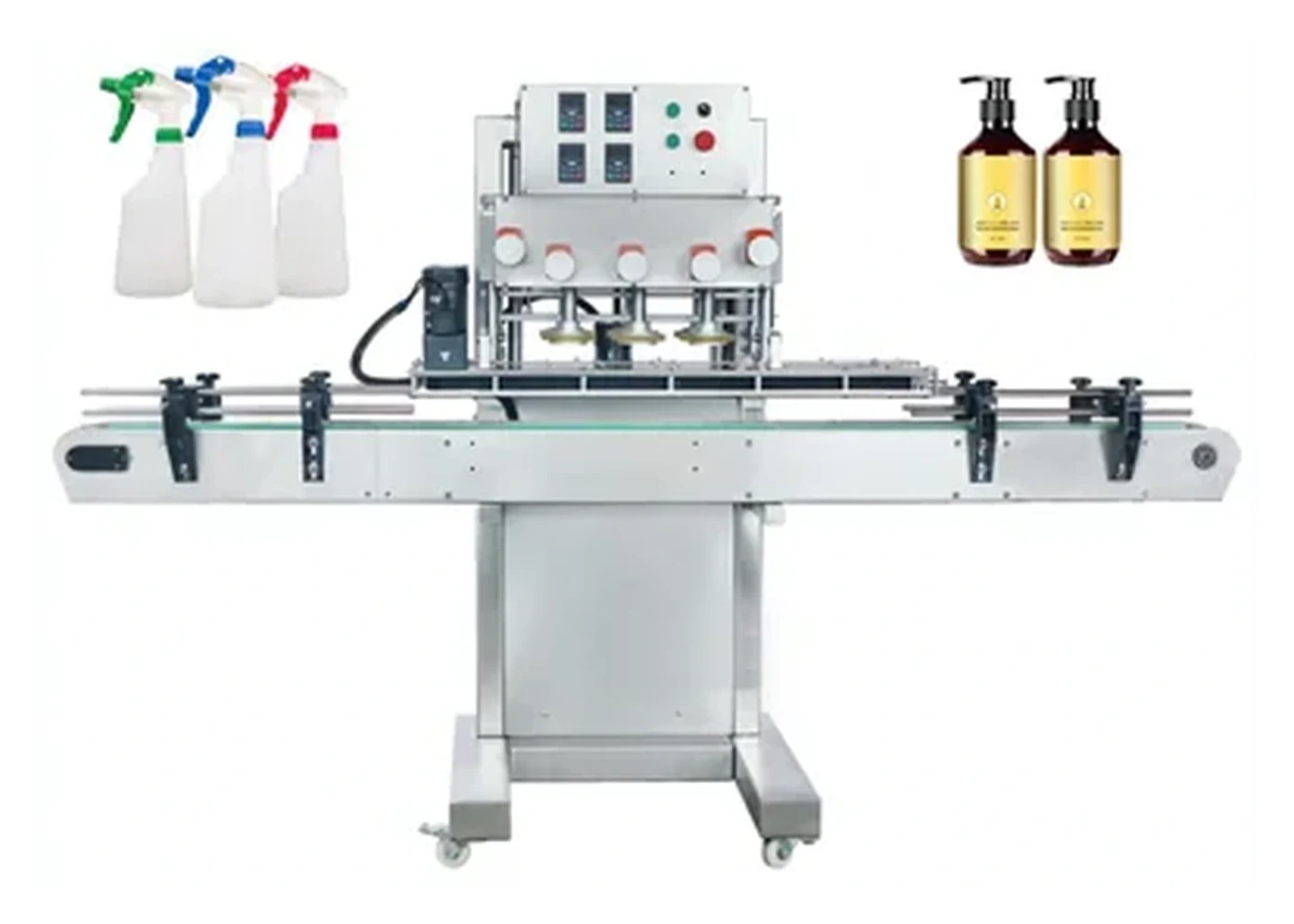
Screw cappers
Flexible automatic capping route for standard screw caps, pump closures and spray bottle formats.
Screw cappers
Space-saving capper for pilot rooms, laboratories and compact packaging areas that need reliable torque control.
Before you ask for a quote
For an accurate recommendation, supply bottle and closure samples or photographs, target output, batch sizes, fill product, bottle dimensions, cap dimensions and notes on any existing line equipment.
| Closure / cap type | Typical machine route | Specification checks |
|---|---|---|
| Threaded plastic screw cap | Screw capper, chuck capper, belt or spindle capper | Torque repeatability, cap height, bottle grip, thread start, changeover time |
| Aluminium ROPP closure | Semi-automatic, automatic or multi-head ROPP capper | Bottle neck finish, skirt length, tamper band, glass stability, roller tooling |
| Pump or lotion pump | Pump bottle capping machine with tube control | Dip-tube length, orientation, cap presentation, bottle stability, tightening torque |
| Trigger sprayer | Trigger sprayer bottle capping machine | Head orientation, tube handling, product sector, container neck and bottle shape |
| Push-on or snap cap | Press capping machine with cap feeder | Vertical force, closure fit, bottle support, cap nesting and feeder orientation |
FAQs
Round, square or oval bottles can often be handled, but the final specification depends on bottle stability, cap diameter, cap height, thread style and output target.
Some pump closures can be handled on specialist screw capping machinery, but dip-tube control and cap orientation must be checked first.
Send bottle and cap details, line speed target and photographs of the current production area. Lancing can advise on the most suitable bottle capping machine or complete line route.
Threaded closure engineering
A screw cap can appear fitted while still being cross-threaded, high, under-tightened or damaged. The machine route should match the cap profile and output requirement, then trials should confirm the finished pack rather than relying only on a torque setting.
| Method | How it applies the closure | Important variables | Suitable evidence |
|---|---|---|---|
| Chuck capper | A shaped chuck grips the closure while the bottle is located and the head rotates or the bottle turns. | Chuck fit, vertical pressure, clutch or servo setting, bottle clamp and thread start. | Cap height, thread engagement, cap marking and torque or opening checks across repeated samples. |
| Magnetic or mechanical clutch | The drive slips or limits transmitted torque when the set resistance is reached. | Closure friction, cap temperature, liner, speed, chuck grip and calibration method. | Results at the agreed settings using the specified torque instrument and test timing. |
| Spindle or belt capper | Opposing wheels or belts progressively rotate a pre-threaded cap while the bottle travels inline. | Cap presentation, spindle height, belt pressure, bottle side grip, guide position and line speed. | Sustained run data including skewed caps, bottle scuffing, cap height and rejected packs. |
| Semi-automatic clamping capper | The operator presents the bottle and normally the cap; the machine clamps and completes a controlled cycle. | Operator rhythm, fixture fit, chuck change, head height and cap placement consistency. | Representative batch run including normal loading, changeover and first-off approval. |
Reference model and tooling
| Published item | Reference value | How to use it |
|---|---|---|
| Bottle height | 100–300 mm | Confirm bottle stability, neck position and fixture access with actual samples. |
| Cap diameter | 20–60 mm | Diameter does not confirm chuck fit; cap height, ribs, skirt and thread still matter. |
| Working speed | 20–60 bottles/min, format-dependent | Confirm the sustained operator-and-machine rate for the agreed pack. |
| Cycle | Manual or automatic mode with bottle clamping | Review operator loading, guarding and the required production workflow. |
These figures are current first-party reference data from the Lancing Screw Cappers product page. Final tooling and performance remain subject to the bottle, closure and trial condition.
Use this page for the broad screw-cap decision. For detailed screw-cap models use Lancing Screw Cappers; for inline spindle technology use Lancing Spindle Cappers. This avoids creating competing copies of the same specialist intent.
Screw cap FAQ
A cross-threaded or high cap can create resistance without correct thread engagement. Finished packs should therefore be checked for cap height, alignment, thread engagement, leakage and opening behaviour as well as torque.
Not necessarily. External ribs, taper, height, decoration and material affect grip and marking. A cap-specific insert or chuck may be needed even where nominal diameters match.
Variation can come from cap and bottle tolerances, liner friction, product residue, thread start, chuck slip, clutch setting, bottle movement, speed and the timing or method used to measure the result.
Spindle systems suit many continuous inline applications using pre-threaded closures. A chuck system may be preferable where the cap needs a shaped grip, controlled vertical cycle or batch operation. Samples and line requirements decide the route.
Use a sustained run with representative cap supply and bottle transfer. Count accepted bottles and record cross-threads, high caps, loose caps, scuffing, bottle damage and any feeder or operator interruption.
Send bottle and cap samples, drawings where available, filled weight, required output, approved torque or opening criteria, all formats, production layout and whether caps will be manually placed or automatically fed.