Feeding is often the bottleneck
A fast capper cannot run reliably if caps arrive incorrectly, inconsistently or too slowly.
Cap feeding
Cap feeding equipment for lifting, sorting, orientating and presenting closures to automatic bottle capping machines.
Specification focus
Use this page to narrow the specification around this bottle machinery family before requesting a quote.
A fast capper cannot run reliably if caps arrive incorrectly, inconsistently or too slowly.
Simple screw caps may suit bowl feeding or elevators, while pumps, triggers and awkward closures often need more specialist handling.
The feeder, chute, pick-and-place route and capping head should be specified as a complete system, not separate items.
Relevant equipment
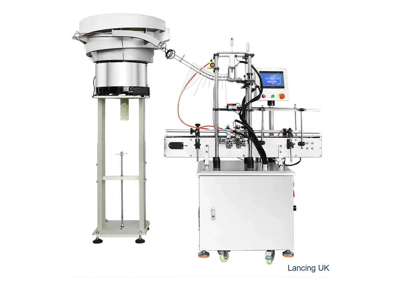
Cap feeding
Automated cap presentation and tightening for threaded caps where manual cap placement would restrict throughput.
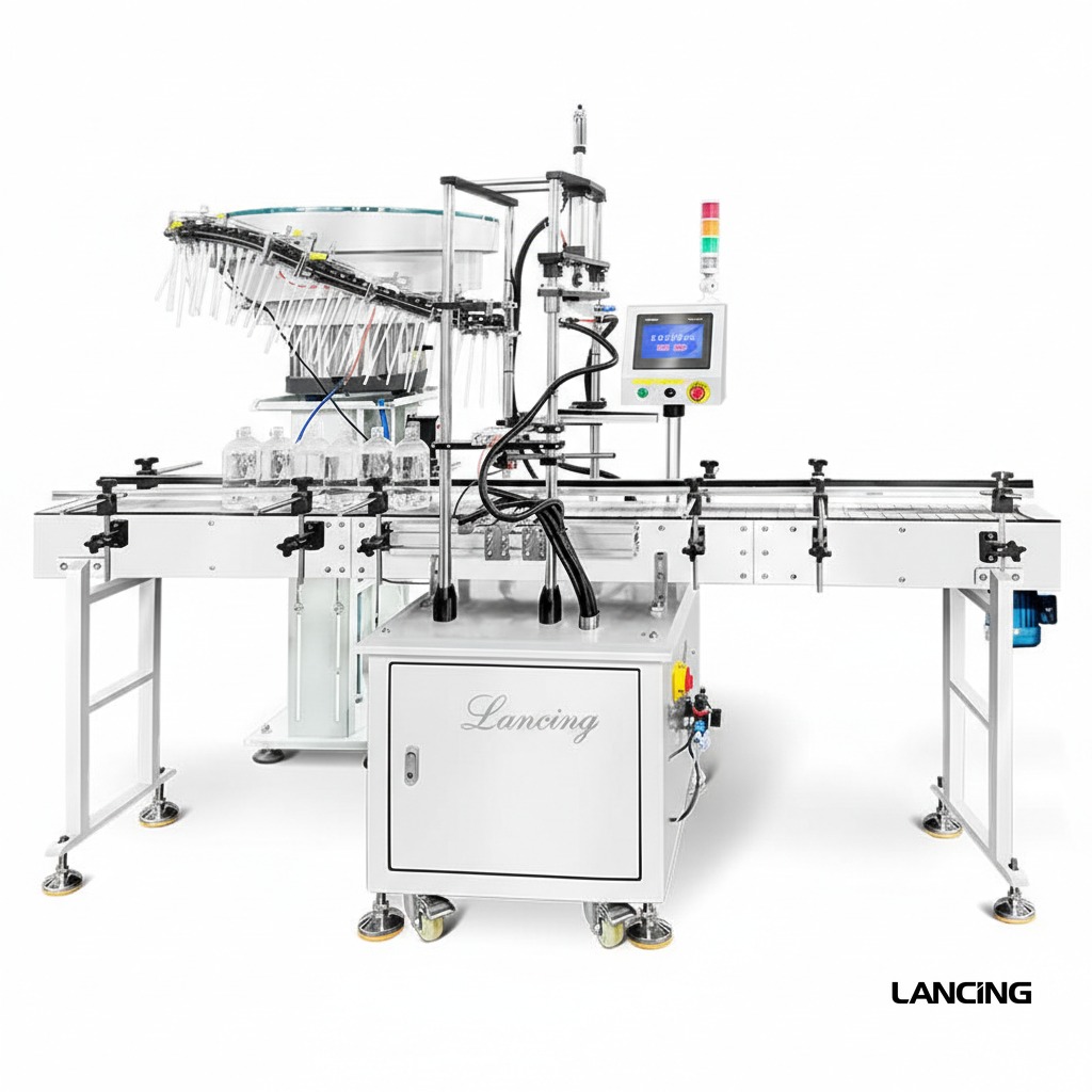
Cap feeding
Dedicated pump cap feeding and presentation equipment for closures that cannot be treated like simple screw caps.
Before you ask for a quote
For an accurate recommendation, supply bottle and closure samples or photographs, target output, batch sizes, fill product, bottle dimensions, cap dimensions and notes on any existing line equipment.
| Closure / cap type | Typical machine route | Specification checks |
|---|---|---|
| Threaded plastic screw cap | Screw capper, chuck capper, belt or spindle capper | Torque repeatability, cap height, bottle grip, thread start, changeover time |
| Aluminium ROPP closure | Semi-automatic, automatic or multi-head ROPP capper | Bottle neck finish, skirt length, tamper band, glass stability, roller tooling |
| Pump or lotion pump | Pump bottle capping machine with tube control | Dip-tube length, orientation, cap presentation, bottle stability, tightening torque |
| Trigger sprayer | Trigger sprayer bottle capping machine | Head orientation, tube handling, product sector, container neck and bottle shape |
| Push-on or snap cap | Press capping machine with cap feeder | Vertical force, closure fit, bottle support, cap nesting and feeder orientation |
FAQs
Most automatic systems need a controlled way to present caps. Some lines can use operator placement, but output and consistency are usually limited.
Sometimes, but it is better to plan cap feeding early so the capper, conveyor and layout are compatible.
Send bottle and cap details, line speed target and photographs of the current production area. Lancing can advise on the most suitable bottle capping machine or complete line route.
Closure supply and recovery
The feeder should separate bulk closures, reject or recirculate incorrect presentations, maintain a useful buffer and recover after normal replenishment or line stops. Its sustained performance must be assessed together with the capper and the actual production closures.
| Feeding route | Typical strength | Compatibility questions | Evidence to collect |
|---|---|---|---|
| Vibratory bowl | Sorts and orients many closures using a dedicated bowl and track. | Can caps separate without nesting, scuffing, bridging or unstable orientation? | Correct presentation, recirculation, jam rate, noise, cap condition and recovery across a sustained run. |
| Cap elevator | Lifts bulk caps and can reduce manual loading height or provide a simpler orientation route. | Does the cap geometry allow reliable pocketing, discharge and transfer to the chute or capper? | Fill-level behaviour, incorrect discharge, transfer stability and restart after depletion. |
| Centrifugal or rotary sorter | Can support higher-output applications with suitable cap geometry. | Are cap material, shape, orientation features and target speed compatible with the sorting principle? | Sustained accepted-cap rate, cap damage, false accepts and changeover evidence. |
| Manual cap placement | Low tooling complexity for batches, trials and difficult closures. | Can the operator sustain the target safely and consistently without becoming the line constraint? | Representative operator cycle, ergonomics, staffing, cap-placement quality and batch completion time. |
| Pick-and-place presentation | Useful for pumps, triggers or closures needing controlled orientation and insertion. | Can the feeder present the body and any dip tube without damage or loss of orientation? | Tube condition, placement accuracy, orientation, missed picks and stop/restart recovery. |
Feeder acceptance test
Load a representative quantity and observe nesting, bridging, tangling and surface damage.
Measure accepted caps delivered to the capper, not only feeder vibration or elevator movement.
Add closures using the intended production method and confirm that the line remains controlled.
Exercise blocked, starved and short-stop conditions and check buffer and recirculation behaviour.
Check marking, deformation, liner displacement, tube damage and incorrectly presented parts.
For a trigger-specific feeder, the current Lancing LU-XG446S reference publishes an approximate Ø15–35 mm cap range, bottle height around 10–280 mm and 20–25 bottles/min, subject to actual closures and transfer design. See the first-party trigger feeder page.
Identify bowl or elevator tooling, tracks, air jets, sensors, escapements, grippers, tube guides and capper transfer parts for every agreed format. Link feeder requirements to the machine range and include them in the quotation checklist.
Cap feeder FAQ
No. Height, mass, external features, material, liner, centre of gravity, nesting, surface finish and the required orientation all affect whether a feeder can sort and transfer the closure reliably.
Useful capacity is the accepted, correctly oriented closure rate delivered to the capper under representative conditions. It should include normal recirculation, replenishment and short stops rather than only the sorter’s theoretical movement.
Packaging variation, static, deformation, surface finish, contamination, storage condition or dimensional tolerance can change bulk behaviour. Keep batch information and compare good and failed closures physically.
Depending on the design, change parts may include bowl tooling, elevator pockets, tracks, rails, air jets, sensors, escapements, chutes, grippers, pick heads and transfer components.
The buffer should support the agreed response to replenishment and normal micro-stops without creating excessive cap pressure or damage. It should be defined from the whole line behaviour rather than as an isolated volume.
Manual placement can be practical for low-volume batches, trials, frequent unusual formats or closures that are disproportionately difficult to orient automatically. Ergonomics and sustained labour demand should still be measured.